
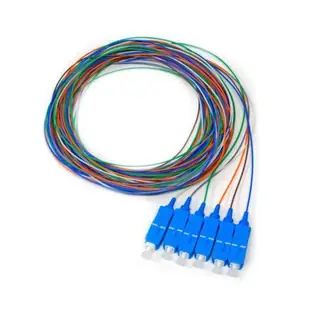
Matching fiber pigtails, splice trays and panel adapters
A pigtail has a factory-terminated connector on one end and fiber for splicing on the other. If a backbone arrives without connectors, count incoming fibers, required front-panel ports and the splice positions your enclosure can accommodate.
What needs to match the installed cable?
Specify single-mode or the appropriate multimode grade, buffer construction, connector family and polish. A six-strand pigtail set and a twelve-position tray describe different parts of the job. Ask whether the quoted quantity counts individual fibers, fan-out assemblies or complete trays.
Will the whole assembly fit behind the panel?
Check tray mounting points and covers against the enclosure model. Account for the protected splice length, routing space and the fiber that must reach each adapter. Record the mapping from incoming strand to front port when handing the job to operations.
Why count pigtails and spares separately?
A planned spare strand might be parked unconnected, spliced to a pigtail or fully presented at a front-panel adapter. Those options consume different components. Have the designer mark the intended condition of every reserve strand so the quantities of pigtails, protectors and adapters agree.
Plan the front of the panel and the splice tray together
For a six-fiber termination, count one termination for every fiber the design brings into service and account separately for future spares. The 15F1-00106 lists six single-mode SC/UPC pigtails at three meters. Check whether the patch-panel couplers and the mating cords use the same connector and polish. Confirm the tray’s splice capacity, the enclosure’s accepted tray model and how slack will be stored. Keep the fiber-to-port schedule with the order. That single sheet allows the splicing technician and the person labeling the front panel to use the same strand numbering.
Documenting a partial termination for future expansion
A backbone can arrive with twelve strands while only four are needed for the first tenant. Decide which fibers will be spliced and presented at the panel today and which will remain reserved in the enclosure. Record strand colors or numbers, splice positions, pigtail connector types and front adapter locations for the fibers actually completed. For the reserves, note whether a pigtail is already fitted and what tray space is available. Otherwise a later material count may treat every unused front port as a ready-to-patch fiber. When a tenant adds a second switch, the schedule will clarify whether the work calls for a jumper, more pigtails, another tray or a new panel insert. Ask the installer to indicate any required additional closure or splice-protection components on that expansion quote.
Compare parts for your setup
6 Strand Fiber Pigtail, 9/125 Singlemode(Blue Boot), SC/UPC, 3 meter
15F1-00106
- Connector references
- SC/UPC
- Configuration
- 6 Strand
- Fiber specification
- 9/125 · Singlemode
- Length
- 3 m
Plan the enclosure’s splice positions for the 6 strands listed for this assembly and match its connectors to the adapter plate.
Check fiber mode, connector and polish at the panel, plus compatibility with the installed fiber.
40mm Fusion Splice Sleeves, 50 Pack
31F1-04050
- Dimensions in listing
- 40mm
- Package quantity
- 50 Pack
Outfit a termination enclosure with pigtails, protective sleeves and a tray suited to its splice layout. The pack contains 50 pieces; count the parts required per installation.
6-Fiber Ribbon/Buffer Tube Fan-Out Kit, Color Coded 36 inch Tubing Length Accepts 250um
15F3-01206
- Configuration
- 6-Fiber
- Dimensions in listing
- 36 inch


