
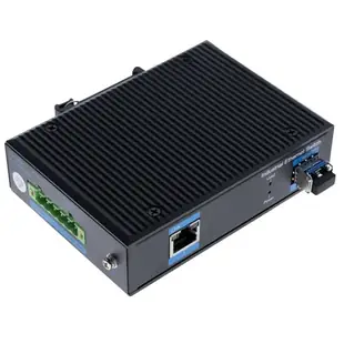
Connecting a copper Ethernet device across an existing fiber route
An outbuilding may have a working optical route, while a printer, camera controller or switch only presents RJ45 Ethernet. Identify the required copper-side speed before choosing the optical handoff.
Will a Fast Ethernet unit slow the link?
A fixed 10/100 converter and a Gigabit model support different Ethernet rates. If the existing link is supposed to carry Gigabit traffic, check both converters or the far-end switch optic. Compare the power supply, cabinet space and the servicing arrangement at each end.
Is an SFP included?
An unloaded slot allows a compatible optic to be chosen separately. Record fiber mode, strands, connectors, wavelength and supported reach. For trouble tickets, document the converter and installed module as separate parts so a replacement order identifies the failed component.
Where can an outage be narrowed down?
Write down the normal copper and optical link indicators at both ends while service works. If one device later loses its connection, compare those indicators and confirm power before replacing the converter. Store the optic model and fiber patch details with the diagram to speed selection of a spare.
Joining the copper network in one room to fiber in another
Sketch the electrical and optical ends separately. The network switch may negotiate a copper speed while the far-end optical equipment expects a fixed optical mode. Part 71F1-103SC lists Fast Ethernet over an SC multimode connection at 850 nm. Compare those details to the actual far-end device, installed fiber and required throughput before ordering a pair. Include power and shelf space for any standalone converter. If a cabinet already has a compatible optical switch port, confirm whether the design needs one converter or two. Counting physical endpoints alone can double the equipment order.
Why would the copper link show activity while the far end is offline?
Treat the converter as two interfaces that must each establish a compatible link. Identify the copper port and its supported speed, then record the optical values from the equipment at both ends. A local light on the copper side can confirm a neighboring device without confirming that the optical path is complete. Compare the converter’s documentation for the exact meaning of its indicators. Verify fiber mode, patch routing and transmit/receive pairing from the site’s records. Test with a known compatible short optical patch under the site’s service procedure before concluding that the building fiber is damaged. If a converter has to be replaced, list the remote unit or module in the request as well. That gives purchasing a complete optical pairing to match when the exact original model is unavailable.
Compare parts for your setup
1 Gigabit Fiber Media Converter, Industrial, Singlemode Duplex 1310nm, 1 SFP included and 1 RJ45 Port, 20km
71F1-53SFP
- Connector references
- RJ45
- Configuration
- Duplex
- Fiber specification
- Singlemode
- Data rate
- 1 Gigabit
1.25 Gigabit Fiber Media Converter Loaded, Singlemode 1310nm(LC DOM), SFP to Multimode 1310nm SFP(LC DOM), Dual SFP Module included
71F1-76SFP
- Connector references
- LC
- Fiber specification
- Singlemode · Multimode
- Data rate
- 1.25 Gigabit
1 Gigabit Fiber Media Converter, Singlemode/Multimode, SFP Slot, Unloaded
71F1-52SFP
- Configuration
- Unloaded
- Fiber specification
- Singlemode · Multimode
- Data rate
- 1 Gigabit


